
Induction preheater for extrusion coating lines of electrical cables
Among the various technological steps involved in the production of electrical cables, the heat treatment of the metal wires that make them up, such as copper, aluminium, etc., takes on considerable importance, which, during the drawing process, changes the physical properties of conductivity, corrosion resistance and reduced ductility.
The work hardening of the conductor also reduces its valuable flexibility in use, hence the imperative need for heat treatment to restore its crystalline structure.
INTECH Automazione Sistemi s.r.l. has considerable experience in the construction and automation of switchboards for copper and aluminium wire drawing plants, roughing machines, intermediate drawing machines and capillary drawing machines, with associated continuous annealing controls.
The company has been active for years in producing electrical cables with the realisation of complex systems for single and triple extrusion coating lines (polymers, fluorinated, fibres).
Because of the frequent need to introduce in-line, before the extruder, low-temperature heat treatment of the wire, we decided to propose our model of induction preheater, called CLIP-H (acronym of Contact Less Induction Pre-Heater).
The main features of the CLIP-H preheater
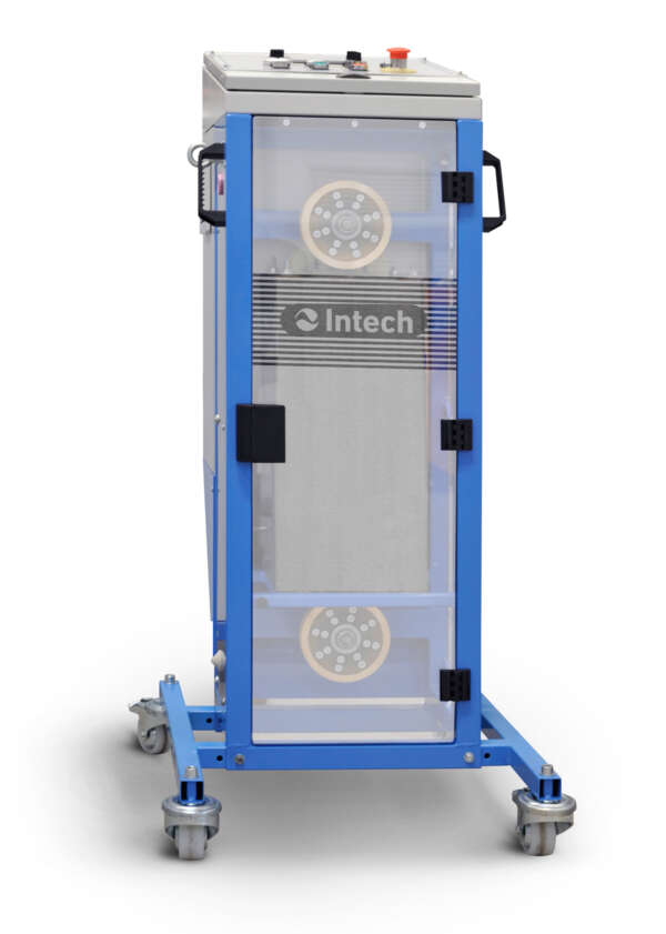
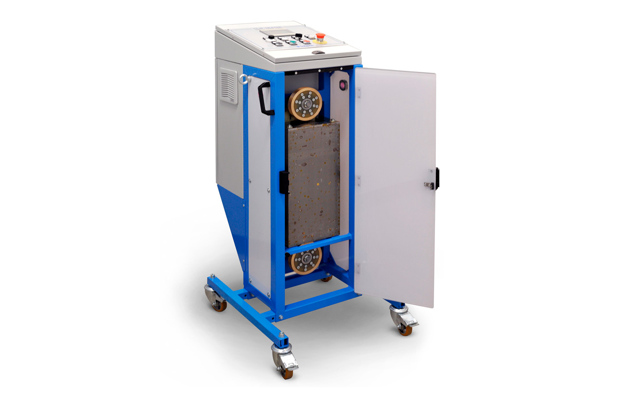
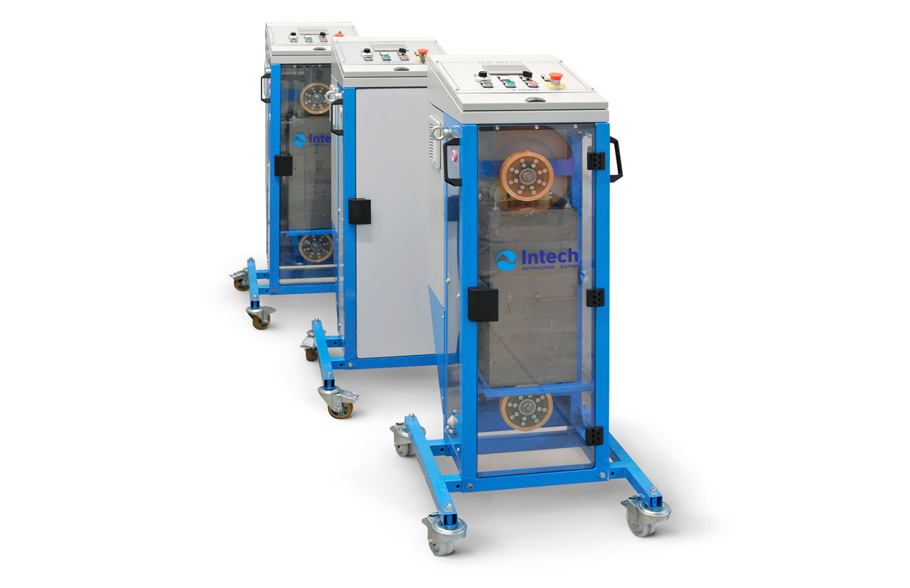
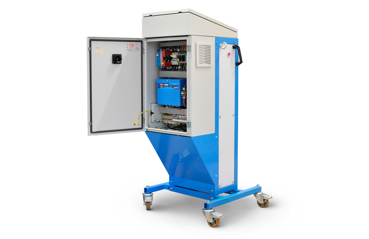
The operating principle is based on the device’s ability to supply the conductor with constant thermal energy regardless of the line speed.
The transfer of power takes place by ‘conduction’, i.e. the wire is traversed, in the heating section, by an electric current by electromagnetic induction supplied by a special transformer, in which the secondary winding is represented by the loop(s) of the conductor itself.
The transformer is powered on the primary winding by an industrial frequency static converter and variable voltage, J-DRIVE series, with delicate and precise control of output current and voltage.
Since the wire does not perform mechanical work, the energy supplied is translated into heat by the Joule effect and the determines the heating.
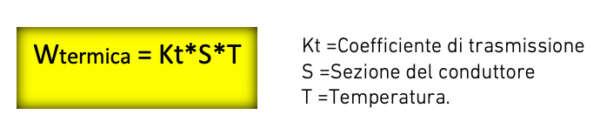
Heat dissipation takes place on the surface of the conductor, and since it is low temperature, the existence of linearity and proportionality between power dissipation and temperature, supported by the following expression:
From Electrical Engineering, Ohm’s law takes us back to the equality between the Amount of Energy in Joules/sec and power expressed in Watts and, wanting to evaluate the capacity to be transmitted to a conductor of cylindrical shape and resistance known; one must refer to the fundamental law expressed by Watt = V * I and best represented by the better-known expression:

which, recalling the formula defining electrical resistance as R = ρ*ℓ/S, is simplified to Watt = k*V2, a formula which clearly shows that, for a given length and cross-section of the wire, power is proportional to the square of the applied voltage.
It follows that the transfer of an amount of energy in Joules/sec (Watts) to a conductor moving at variable speed, with fixed length (distance between pulleys) and known resistance, modifies the previous expression to m/sec = k*V2 giving rise to the following law which expresses, in quadratic form, the value of the preheater output voltage as a function of the line speed.

The generation of this law is easily implemented through a PLC programmable controller, which, through a colour HMI interface, allows the tracing of programmable curve families for each conductor and material type, starting from a stored primary quadratic curve.
Finally, a signal is sent from the PLC to the J-DRIVE static device, delivering the required heating power.
Further consideration should be made by returning to the initial power formula Watt = V2/R where, by replacing R with the corresponding representation showing resistivity coefficient, length and cross-section of the wire
R = ρ * ℓ/S
ρ = Material resistivity (rho)
ℓ = Conductor length
S = Conductor cross-section (S=πr2)
Note that the heating power is directly proportional to the cross-section; the programmed heating curve needs to be shifted up or down for the same type of wire without changing the stored curve profile.
ELECTRICAL CHARACTERISTICS
Power Section
– J-DRIVE static power converter
– Power supply 2 x 400V-50/60Hz
– Disconnector with door lock
– Power 15 kW
– Current 37/45Amp
– Adjustable overload limitation
– Voltage accuracy < 0.1%
– Extra rapid current protection
– Galvanic isolation Power/Control
– Digital line speed transducer
– Internal ventilation with filters
– Access Door Security Module
Sezione Software
– Siemens S7-1200 controller
– Profinet interface
– Operating Modes: Constant voltage – Variable voltage
– Generation of Quadratic Curve Families
– Manual mode tracing preheating curves
– Digital line speed acquisition
– Galvanic isolation Power/Control
MECHANICAL CHARACTERISTICS
Structure
– Tubular steel supports
– Lateral lifting eyebolts
– Swivel castors with a parking brake
– Drag handles
– Total height mm 1308
– Pass line mm 1045
– Width mm 400
– Adjustable base supports L= mm 573 – 453
– Total depth mm 705
– Ceramic wire inlet-outlet bushings
– Plexiglass side guards
– Front door with transparency screen printing
– Electric lock
Quadro Elettrico
– Dimensions mm 600 x 400 x 200
– Command desk mm 155 x 495 x 60 inclined 11°
– Cable entry from below
– Cable entry protection removable ½ threaded knobs
Pulpit operator
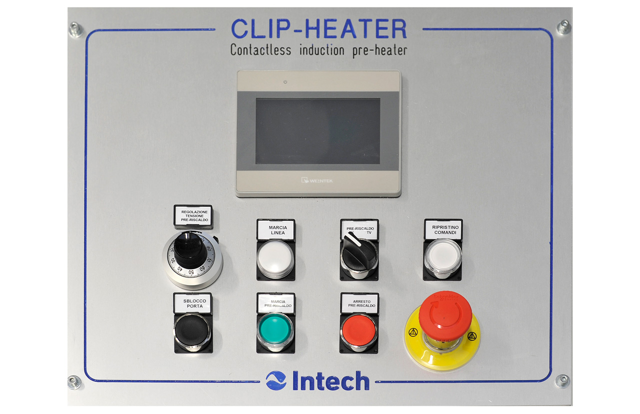
4” T.S. HMI colour operator interface for LECTERN PANEL:
– Preheating curve tracing
– Setting recipes
– Line speed setting
– Setting wire section
– Line speed display
– Primary transformer voltage display
– J-Drive output current display
– Fault display
–
Commands
– Illuminated switch-on/reset button
– Running line warning lamp
– Potentiometer Tracking Preheating Curves
– Constant voltage/Variable voltage mode selector
– Start-Stop buttons CLIP-H
– Door release button
– CLIP-H Emergency Mushroom (Function extended to Emergency Line: optional with activation from HMI)
Future developments
There is ongoing research and investigation into non-contact temperature sensing devices, e.g. cameras and infrared transducers, for small diameter wires (<5mm),
The aim is to realise, in addition to the temperature display, complete closed-loop control of the temperature from the PLC with feedback directly from the sensor.
The open-loop control system will, of course, be maintained, as in the current units, in the event of a temperature detector failure.
In case of special customer requests, we are able to develop and modify CLIP-H to adapt it to any need by developing custom solutions.
Download data sheet